Walk into any engineering office and you'll find stacks of piping and instrumentation diagrams. Every line, symbol, and label on those drawings follows a system. That system is ISA 5.1. Without it, a P&ID drawn in Houston would look like a foreign language to an engineer in Seoul. If you've ever stared at a P&ID and wondered what a specific tag number or symbol actually means, the answer almost always traces back to this standard.
ISA 5.1 published by the International Society of Automation defines how instrumentation symbols, identification letters, and tag numbers are used on piping and instrumentation diagrams. It's the shared language that keeps process engineers, instrument technicians, control system designers, and piping designers all reading the same page. Getting it wrong doesn't just cause confusion. It causes project delays, miscommunication in the field, and in worst cases, safety incidents.
What Exactly Does ISA 5.1 Cover?
At its core, ISA 5.1 is a symbol and identification standard. It specifies three main things:
- Graphical symbols the shapes used to represent instruments, control valves, transmitters, switches, and other devices on a P&ID
- Identification letters the letter codes (like "PT" for pressure transmitter or "FCV" for flow control valve) that go inside instrument bubbles
- Tag number formats how to combine loop numbers, prefixes, and suffixes to create unique instrument identifiers
The standard also addresses how these symbols connect to piping, where signals are shown, and how to indicate instrument location (in the field, in a control room, on a panel, etc.). If you're trying to make sense of common P&ID abbreviations, ISA 5.1 is the source document those abbreviations come from.
Why Should a Process Engineer Care About This Standard?
You might think notation is just a drawing detail. But P&IDs are legal, contractual documents. They're used for:
- Safety reviews HAZOP studies rely on accurate P&IDs to identify hazards
- Procurement instrument specifications and valve orders are based on what's tagged on the P&ID
- Construction field teams install equipment according to the drawings
- Operations and maintenance operators use tag numbers to request work orders and troubleshoot
- Regulatory compliance agencies like OSHA and the EPA reference P&ID accuracy in Process Safety Management
A misidentified instrument on a P&ID can mean the wrong valve gets ordered, the wrong setpoint gets programmed, or a safety interlock gets bypassed during maintenance. The stakes are real.
How Do ISA 5.1 Identification Letters Work?
This is where most people first encounter the standard. ISA 5.1 uses a structured letter code system. Each instrument tag is built from letters that describe its function:
- First letter identifies the measured or initiating variable (e.g., T = Temperature, P = Pressure, F = Flow, L = Level)
- Successive letters describe the function (e.g., T = Transmit, C = Control, I = Indicate, A = Alarm, S = Switch)
For example, TIC-101 breaks down as: Temperature (T), Indicate (I), Control (C), in loop number 101. That tells you it's a temperature indicating controller in loop 101. A PSV-205 is a Pressure Safety Valve in loop 205.
You can explore a full breakdown of how to read instrumentation loop diagram codes if you want a step-by-step walkthrough of these letter combinations.
What Do the Bubble Symbols Mean on a P&ID?
ISA 5.1 defines instrument symbols using circles (often called "bubbles"). The shape and placement of the bubble communicates important information:
- Circle with a horizontal line through it the instrument is located on a main panel in the control room
- Circle with no line the instrument is mounted in the field
- Circle with a flag or diamond shape indicates shared display or auxiliary panel locations
- Hexagon used for computer or PLC-based functions in some interpretations
Lines connecting these symbols indicate signal types dashed lines for electrical signals, double lines for pneumatic signals, and so on. These visual cues let a reader scan a drawing and quickly understand how a control loop is physically and logically connected.
When Did ISA 5.1 Come From, and Is It Still Current?
ISA 5.1 has been around since the 1950s, with multiple revisions over the decades. The most widely referenced version is ISA-5.1-2009 (R2019), reaffirmed in 2019. While the core framework has remained stable, updates have added clarity on digital instruments, distributed control systems (DCS), and programmable logic controllers (PLCs) technologies that didn't exist when the standard was first written.
It's worth noting that ISA 5.1 works alongside other standards. For example, ISA 5.4 covers instrument loop diagrams, and ISA 5.5 covers graphic displays for process control systems. On the international side, IEC 62424 and ISO 14617 provide related frameworks, though ISA 5.1 remains the dominant standard in North American process industries like oil and gas, chemical manufacturing, and power generation.
What Are the Most Common Mistakes People Make With ISA 5.1?
After reviewing P&IDs across dozens of projects, here are the errors that show up again and again:
- Mixing up identification letter order writing "ICT" instead of "TIC" for a temperature indicating controller. The first letter must always be the measured variable.
- Using inconsistent loop numbers assigning loop 101 to a temperature instrument in one area and then reusing 101 for a flow instrument in another area. Each tag must be unique on a project.
- Confusing signal line types drawing a solid line where a dashed line should be, making it unclear whether a signal is electrical, pneumatic, or software-based.
- Skipping the instrument location bubble detail leaving out the horizontal line that shows whether an instrument is field-mounted or panel-mounted. This matters during construction.
- Not updating P&IDs after field changes the "redline problem." When as-built conditions drift from the drawing, the P&ID loses its value as a reliable reference.
These mistakes are easy to prevent with a clear understanding of the ISA 5.1 notation standards and a disciplined review process.
How Does ISA 5.1 Differ Across Companies and Industries?
ISA 5.1 is a standard, not a rigid template. It provides a framework, but individual companies and engineering firms often create their own project-specific P&ID legend sheets that refine the standard for their needs. For example:
- A refinery might use specific line-shading conventions for different process fluids
- A pharmaceutical company might add GMP-specific notations for clean-in-place systems
- An EPC contractor might define a unique loop numbering scheme tied to plant areas
The key is that these project conventions should build on ISA 5.1, not contradict it. When you pick up a P&ID from any reputable engineering firm, the symbol grammar should be recognizable if you know the ISA standard.
Practical Tips for Working With ISA 5.1 Notation
Here are a few habits that make a real difference:
- Always start with the P&ID legend sheet before reading any drawing, study the legend. It tells you exactly how that project interprets and extends ISA 5.1.
- Memorize the common first letters P (pressure), T (temperature), F (flow), L (level), A (analysis), and D (density or differential). These cover the vast majority of instruments you'll encounter.
- Keep a personal abbreviation reference build a quick-reference card of identification letter combinations. It speeds up P&ID reading significantly.
- Cross-check with instrument data sheets the tag on the P&ID should match the tag on the instrument datasheet, loop diagram, and DCS configuration. Inconsistency here is a red flag.
- Use version control always verify you're reading the latest revision of a P&ID. Old drawings in the field are a well-known source of errors.
Your Next Step: Build a Personal P&ID Reference
If you work with P&IDs regularly, create a one- or two-page cheat sheet based on ISA 5.1. Include the most common identification letter codes, the bubble symbol variations, and your company's specific conventions. Keep a printed copy at your desk and a digital copy on your phone. It will save you hours of second-guessing over the course of a project.
Quick-Start Checklist for ISA 5.1 Notation
- Download or access the current ISA-5.1-2009 (R2019) standard from the ISA website
- Study the P&ID legend sheet for your current project before reading any drawings
- Learn the six most common first letters: P, T, F, L, A, D
- Practice reading tag numbers aloud say each letter's meaning out loud until it becomes automatic
- Verify that tag numbers match across P&IDs, datasheets, loop diagrams, and control system databases
- Keep a log of notation questions that come up in design reviews and resolve them against the standard
- Share your project's legend sheet with every team member who touches the P&IDs including field contractors
Consistency is what makes a P&ID useful. ISA 5.1 gives you the rules. Applying them carefully is what turns a drawing into a reliable communication tool that holds up from design through decades of plant operation.
 Step-By-Step Guide to Reading Loop Diagram Codes
 Chemical Plant P&id Notation Legend & Instrumentation Code Reference
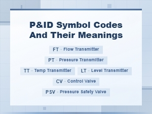 P&id Symbol Codes and Meanings: Complete Guide to Piping and Instrumentation Diagrams
 Common Piping and Instrumentation Diagram P&id Abbreviations for Process Engineers
 Circuit Diagram Symbols and Their Meanings Explained
 Common Electronic Component Symbols Used in Wiring Diagrams