If you've ever stared at a piping and instrumentation diagram and felt lost in a maze of symbols, circles, and letter codes, you're not alone. Chemical plant P&ID notation and instrumentation codes are the shared language of process engineering. Without a solid grasp of the legend and code systems, even experienced engineers can misread a drawing, leading to wrong valve selections, incorrect control logic, or costly field installation errors. This reference breaks down what those symbols and codes actually mean, how they're organized, and how to use them on real projects.
What Does a Chemical Plant P&ID Legend Actually Include?
A P&ID legend is the key that sits in the corner or on the first sheet of every piping and instrumentation drawing. It translates the shorthand symbols used throughout the diagram into plain meaning. In a typical chemical plant legend, you'll find representations for:
- Piping symbols different line types for process lines, utility lines, instrument air, and signal connections
- Valve symbols gate, globe, ball, butterfly, check, and relief valves, each with a distinct shape
- Vessel and equipment symbols tanks, columns, heat exchangers, pumps, and compressors
- Instrumentation identifiers circles, diamonds, and hexagons indicating field-mounted, panel-mounted, or DCS/PLC-based instruments
- Signal line types solid, dashed, and dotted lines that show electrical, pneumatic, hydraulic, or software connections
The legend is not optional reading. It's the first place you should look before interpreting any P&ID sheet. Without it, you're guessing.
How Are Instrumentation Identification Codes Structured?
Instrumentation codes on P&IDs follow a standardized naming system rooted in ISA/ANSI 5.1. Each instrument tag is built from a combination of letters, each carrying a specific meaning based on its position in the tag.
What Do the Letters in an Instrument Tag Mean?
A typical tag like FIC-101 breaks down like this:
- First letter (F) Measured variable. F = Flow
- Second letter (I) Modifier. I = Indicating
- Third letter (C) Output function. C = Controller
- Number (101) Loop number assigned by the engineering team
Other common first letters include T (temperature), P (pressure), L (level), A (analysis), D (density), and C (conductivity). The letters that follow describe what the instrument does with that measurement whether it transmits, indicates, records, controls, or alarms.
If you want a deeper walkthrough on reading these codes in full loop context, our step-by-step guide on reading instrumentation loop diagram codes covers that in detail.
Why Do Chemical Plants Use Standardized P&ID Notation?
Standardization exists so that a P&ID drawn in Houston can be read by an engineer in Mumbai, a fabricator in Seoul, and an operator in Rotterdam all understanding the same symbols without confusion. This matters because:
- Safety Misidentifying a symbol for a safety relief valve versus a control valve can lead to overpressure risks.
- Procurement Incorrect tag interpretation leads to wrong equipment orders, schedule delays, and wasted budget.
- Operations Control room operators depend on accurate tag naming to respond to alarms and troubleshoot upsets.
- Regulatory compliance Agencies like OSHA and the EPA reference P&IDs during Process Safety Management (PSM) audits.
The standards behind this system are maintained by ISA (International Society of Automation). The most widely used is ISA 5.1 for P&ID notation standards, which defines symbol shapes, tag structures, and drawing conventions.
What Are the Most Common P&ID Symbols People Get Wrong?
Even with a legend available, certain symbols cause repeated confusion on chemical plant projects:
- Gate valve vs. globe valve Both look similar at first glance. A gate valve has a simple wedge shape; a globe valve has a more rounded body. Getting this wrong means specifying the wrong valve for throttling service.
- Normally open vs. normally closed valves The position of a diagonal line through the valve symbol indicates its fail state. Misreading this can cause hazardous scenarios during power or air failure.
- Field-mounted vs. panel-mounted instruments A circle with a horizontal line through the bottom means field-mounted. A circle inside a square means it's in a shared display or DCS. These distinctions matter during construction and commissioning.
- Signal line types A dashed line could mean pneumatic, electrical, or software signal depending on the specific standard the project follows. Always check the legend first.
- Double vs. single acting actuators Actuator symbols for spring-return versus double-acting look different and have serious implications for fail-safe design.
When Should You Reference the P&ID Legend and Instrumentation Codes?
You need this reference in several real-world situations:
- During front-end engineering (FEED) When developing preliminary P&IDs and establishing the instrument numbering system for the project.
- During detailed design When instrument engineers are building loop diagrams, data sheets, and wiring schedules based on P&ID tags.
- During HAZOP reviews When safety teams walk through each node on the P&ID and need to understand every instrument's function and location.
- During construction and commissioning When field teams use red-lined P&IDs to verify correct installation against design intent.
- During troubleshooting When operators or maintenance teams trace a control loop from the field instrument back to the control system to find a fault.
For a broader overview of all the notation types you'll encounter, our full P&ID notation legend and instrumentation code reference is a solid resource to bookmark.
How Do Different Companies Customize P&ID Legends?
While ISA 5.1 provides the baseline, most engineering firms and owner-operators layer their own conventions on top. Common customizations include:
- Project-specific instrument numbering Some use area codes (e.g., 100 for utilities, 200 for reaction area), others use unit-based numbering.
- Company-specific symbol additions Symbols for proprietary equipment, packaged units, or vendor-specific devices not covered by ISA standards.
- Color coding Some organizations use color on P&IDs to distinguish utility systems (blue for cooling water, red for steam, green for instrument air), though black-and-white versions are still common for official issue.
- Legend sheet variations Some projects put the legend on every sheet; others include it only on the first sheet of a set.
The key takeaway: never assume a symbol means the same thing across different projects. Always check the project-specific legend.
Practical Tips for Working With P&ID Notation and Instrument Codes
- Print the legend sheet and keep it at your desk. Digital P&IDs in software like SmartPlant or Aveva make it easy to zoom and click, but having a paper legend speeds up reference during reviews.
- Learn the first-letter and second-letter logic by heart. Once you internalize the ISA 5.1 letter table, reading tags becomes second nature.
- Cross-reference tags with instrument index lists. A tag on the P&ID should match an entry in the instrument data sheet and index. Discrepancies are red flags.
- Watch for revision clouds. When reading a P&ID, always check the revision block. An outdated drawing may have incorrect symbols or tags that were changed in a later revision.
- Ask for the legend before asking questions. If you're joining a project mid-cycle, get the legend sheet and drawing standards document first. It saves hours of confusion.
Quick-Reference Checklist: P&ID Legend and Instrument Code Essentials
- ✅ Locate and review the legend sheet before reading any P&ID
- ✅ Know the ISA 5.1 first-letter table (F, T, P, L, A, D, etc.) and what each subsequent letter means
- ✅ Distinguish between field-mounted, panel-mounted, and DCS-based instrument symbols
- ✅ Identify signal line types (electrical, pneumatic, software) from the legend, not from memory
- ✅ Check valve fail-safe position symbols the diagonal line matters
- ✅ Verify the project-specific numbering convention before assuming loop numbers follow a pattern
- ✅ Cross-check every P&ID tag against the instrument index and data sheets
- ✅ Confirm you're reading the latest revision by checking the revision block on each sheet
- ✅ Keep a printed legend sheet accessible during HAZOP, design reviews, and field walkdowns
- ✅ When in doubt, go back to the ISA 5.1 standard it's the foundation everything else is built on
Next step: Pull up a current P&ID from your project, open the legend sheet side by side, and trace five instrument tags from their field location through the control system. If any tag doesn't match the instrument index, flag it. That small exercise builds real fluency faster than memorizing symbol charts.
 No Analysis, No Counting, No Explanation, No Quotes, and It Should Be Max 100 Characters.
 Step-By-Step Guide to Reading Loop Diagram Codes
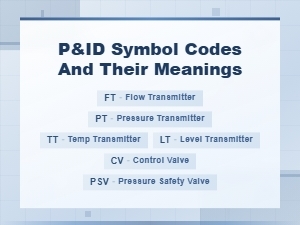 P&id Symbol Codes and Meanings: Complete Guide to Piping and Instrumentation Diagrams
 Common Piping and Instrumentation Diagram P&id Abbreviations for Process Engineers
 Circuit Diagram Symbols and Their Meanings Explained
 Common Electronic Component Symbols Used in Wiring Diagrams