Reading an instrumentation loop diagram can feel overwhelming at first. You're staring at a drawing full of letters, numbers, symbols, and lines and you're expected to understand what every single one means. If you work in instrumentation, process control, maintenance, or engineering, this skill isn't optional. It's the foundation of how control systems are wired, installed, tested, and troubleshooted in real plants. Learning how to read instrumentation loop diagram codes step by step saves you hours of confusion on the job and helps you trace any signal from field device to control room without guessing.
This guide walks you through the actual process what each code means, how the parts connect, and how experienced technicians and engineers read these drawings quickly. No jargon for the sake of jargon. Just clear steps you can apply today.
What Exactly Is an Instrumentation Loop Diagram?
An instrumentation loop diagram (sometimes called a loop sheet) is a detailed drawing that shows the complete wiring and signal path for one control or monitoring loop. Each loop connects a field instrument like a transmitter, sensor, or control valve to the control system, such as a DCS (Distributed Control System), PLC, or panel-mounted controller.
The diagram includes everything between the field device and the control system input/output: terminal blocks, junction boxes, marshalling cabinets, cable numbers, signal types, power supply connections, and instrument tags. If you've ever looked at a P&ID symbol code reference, the loop diagram takes those same instrument tags and gives you the full electrical and signal-level detail behind them.
Why Do Technicians and Engineers Need to Read Loop Diagrams?
Loop diagrams are used every day in real plants for specific, practical reasons:
- Installation Electricians and instrument technicians use loop sheets to wire instruments correctly during construction or expansion projects.
- Troubleshooting When a transmitter gives a bad reading or a valve doesn't respond, the loop diagram is the first document you grab to trace the signal path and find the fault.
- Commissioning During startup, every loop is tested against its loop diagram to confirm correct wiring and signal integrity.
- Maintenance planning Knowing the full loop helps you isolate a device safely without affecting other parts of the system.
- Documentation compliance Many industries require as-built loop diagrams for regulatory and safety audits.
What Do the Letters and Numbers in an Instrument Tag Mean?
Every instrument on a loop diagram has a unique tag name and every letter or number in that tag follows the ISA 5.1 standard. This is the universal language of instrumentation. Here's how to break down a tag like FT-101A:
- F Measured variable. "F" stands for Flow. Other common first letters: T (Temperature), P (Pressure), L (Level), A (Analysis), D (Density).
- T Device function. "T" stands for Transmitter. Other common letters: I (Indicating), C (Controller), V (Valve), E (Element/Sensing), S (Switch), A (Alarm).
- 101 Loop number. This is a unique number assigned to that specific control loop.
- A Suffix. Used when there are multiple devices of the same type in one loop (e.g., two flow transmitters: FT-101A and FT-101B).
Understanding this tag structure is the single most important step. Once you can decode the tag, you know what the instrument measures, what it does, and where it fits in the process. For a deeper look at these letter combinations, the chemical plant P&ID notation legend covers the full range of ISA codes and their meanings.
How Do You Read an Instrumentation Loop Diagram Step by Step?
Step 1: Identify the Loop Number and Tag
Start at the top or title block of the loop diagram. Every loop sheet is numbered usually matching the primary instrument's loop number. Find the main instrument tag (e.g., FT-101) and all related devices in that loop (controller, valve, alarm, indicator, etc.). The title block also tells you the drawing number, revision, and project details.
Step 2: Locate the Field Device on the Drawing
Find the field instrument symbol. This is usually drawn near a process line or vessel, or on the left side of the loop sheet. The symbol tells you what kind of device it is a transmitter, thermocouple, control valve, solenoid, etc. The tag name is written next to or inside the symbol. Cross-reference the symbol with standard P&ID symbol codes if you need confirmation.
Step 3: Follow the Signal Path from Field to Control System
Trace the lines from the field device to the control system. On most loop diagrams, you'll see:
- Cable or wire numbers Each cable has a unique number (e.g., C-101 or W-205A).
- Junction box references Shows where cables connect through a terminal box (e.g., JB-301, Terminal TB-5).
- Marshalling cabinet references Shows where the signal lands in the control room wiring (e.g., MAR-2, TB-15).
- Channel or card references Shows which DCS/PLC input or output card the signal connects to (e.g., AI Card 3, Channel 12).
Follow the line and note every connection point. Each point is where a physical wire is terminated and each one is a potential point of failure during troubleshooting.
Step 4: Identify the Signal Type
The diagram shows what kind of signal travels through the loop:
- 4–20 mA The most common analog signal in industrial instrumentation.
- 0–10 V Less common, used in some HVAC and lighter-duty applications.
- HART protocol A digital signal layered on top of the 4–20 mA analog signal, used for configuration and diagnostics.
- Thermocouple (TC) or RTD Temperature sensor signals, shown with specific wire types (Type J, Type K, Pt100, etc.).
- Discrete (on/off) Digital signals for switches, solenoids, and relay contacts.
- Fieldbus / PROFIBUS / Foundation Fieldbus Digital communication protocols used in modern systems.
The signal type determines how the instrument is powered, how it's wired, and what kind of input card it connects to in the control system.
Step 5: Check Power Supply Connections
Many loop diagrams show a 24 VDC power supply feeding the transmitter through the same two wires that carry the 4–20 mA signal (loop-powered). Others may show a separate power connection (line-powered or externally powered). Look for power supply symbols, fuse references, and supply voltage annotations on the diagram. Incorrect power wiring is one of the most common installation mistakes.
Step 6: Read the Notes and Details Section
Most loop diagrams include a notes section or detail boxes that give extra information:
- Instrument range and engineering units (e.g., 0–100 kPa, 0–500 °C)
- Fail-safe action (fail open, fail close, fail in place)
- Cable specifications (type, size, shielding, armor)
- Special installation notes (intrinsically safe wiring, explosion-proof enclosure, etc.)
- Cross-references to other drawings (P&ID number, plot plan, cable schedule)
Never skip the notes. Critical wiring and safety details are often buried there.
Step 7: Verify the Controller or System Side
Follow the signal all the way to the control system terminal. Confirm the input/output type (AI, AO, DI, DO), card number, channel number, and terminal strip reference. This is the final connection point and the one most likely to cause confusion if the diagram is outdated or if field modifications were made without updating the documentation.
Can You Give a Practical Example?
Let's say you're looking at a loop diagram for FIC-201 a Flow Indicating Controller.
- FT-201 A differential pressure flow transmitter installed on a 6-inch process line. It's loop-powered with a 4–20 mA signal.
- The signal travels through cable C-305 to junction box JB-12, Terminal 7 and 8.
- From JB-12, the signal continues through cable C-410 to the marshalling cabinet MAR-1, Terminal Block 9, Terminals 3 and 4.
- At the marshalling cabinet, the signal lands on AI Card 2, Channel 7 of the DCS.
- The DCS processes the signal and sends a control output to FY-201 (an I/P converter) through AO Card 1, Channel 4.
- FY-201 converts the electrical signal to a pneumatic signal that drives FCV-201, a globe control valve with a spring-return actuator that fails closed.
That's one complete loop from process measurement to final control element. Every wire, every terminal, every device is documented on the loop sheet.
What Are the Most Common Mistakes When Reading Loop Diagrams?
- Confusing P&IDs with loop diagrams A P&ID shows the process relationship between instruments and equipment. A loop diagram shows the actual wiring. They use the same tags but serve different purposes.
- Ignoring revision dates Plants change over time. Always check that you're working from the latest revision. An outdated loop diagram can send you down the wrong path.
- Skipping terminal points Every terminal block and junction box is a connection point that can loosen, corrode, or be wired wrong. Don't just skim past them.
- Not checking signal type Wiring a 4–20 mA transmitter to a thermocouple input card (or vice versa) is a real-world mistake that happens more than people admit.
- Forgetting intrinsic safety barriers In hazardous areas, some loops require safety barriers in the signal path. Missing these during wiring can be dangerous and non-compliant.
What Tips Help You Read Loop Diagrams Faster?
- Learn the ISA tag letters cold If you have to look up every tag, you'll be slow. Memorize the first letter (measured variable) and second letter (device function) combinations.
- Use a highlighter or colored pen When tracing a loop, mark each terminal and cable as you go. This prevents you from losing your place, especially on complex loops with multiple junction boxes.
- Cross-reference with the P&ID first Before diving into wiring details, look at the P&ID symbol codes to understand what the loop is measuring and controlling.
- Start at the field device, not the control system The field end is usually simpler and helps you build understanding before you reach the more complex control room wiring.
- Keep a cable schedule and terminal list handy These companion documents fill in details the loop diagram might reference but not repeat.
What Should You Do After Learning the Basics?
Once you're comfortable reading a single loop diagram, practice with loops that have multiple instruments, split signals, or redundant transmitters. Work through loops that include HART communicators, safety instrumented systems (SIS), or fieldbus devices. These add layers of complexity you'll encounter in real plants.
Also, get comfortable with the full instrumentation code reference system used in chemical plants, refineries, and power stations. The more notation you recognize, the faster you'll read any diagram regardless of which facility or engineering firm created it.
For reference, the ISA 5.1 standard defines the instrumentation symbology and letter codes used across the industry. Familiarizing yourself with this standard gives you a solid baseline that applies to every plant you'll ever work in.
Quick-Reference Checklist: Reading an Instrumentation Loop Diagram
- ☐ Find the loop number and title block confirm you have the correct, latest revision.
- ☐ Identify the primary instrument tag and decode each letter (measured variable, device function, loop number, suffix).
- ☐ Locate the field device symbol and confirm instrument type.
- ☐ Trace the signal path from field device through each junction box, cable, and terminal.
- ☐ Identify the signal type (4–20 mA, TC, RTD, discrete, digital bus).
- ☐ Check power supply connections and fuse references.
- ☐ Read all notes, ranges, fail-safe actions, and special installation requirements.
- ☐ Follow the signal to the control system confirm card, channel, and terminal strip.
- ☐ If it's a final control loop, trace through the output to the I/P converter and control valve.
- ☐ Cross-check the P&ID to confirm the loop's process function and interlock relationships.
Print this checklist and keep it in your toolbox. After a few loops, you won't need it anymore but when you're starting out, it keeps you from skipping steps and missing connections.
 No Analysis, No Counting, No Explanation, No Quotes, and It Should Be Max 100 Characters.
 Chemical Plant P&id Notation Legend & Instrumentation Code Reference
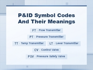 P&id Symbol Codes and Meanings: Complete Guide to Piping and Instrumentation Diagrams
 Common Piping and Instrumentation Diagram P&id Abbreviations for Process Engineers
 Circuit Diagram Symbols and Their Meanings Explained
 Common Electronic Component Symbols Used in Wiring Diagrams